Background
The HCS12 is a micro-controller designed in the the year 2000 by freescale . It was designed as a board for education and is still used by many schools to this day.
The HCS12 is a micro-controller designed in the the year 2000 by freescale . It was designed as a board for education and is still used by many schools to this day.
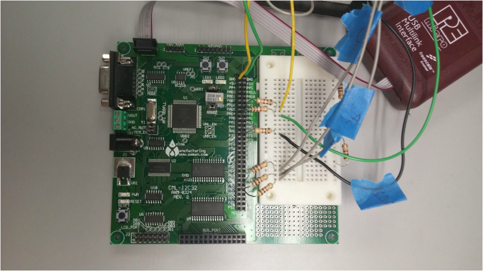
figure 1: The HCS12 in the configuration we used
Implementation
We used the HCS12 as the brain of the system and it was used for the clock pulse, the row selector and the serial out for shift register. Each task was assigned to its own port meaning that the row selector was given port B, the clock was on port A and the serial out was on port P. When you program these ports you have to initialize which pins will be used as inputs or outputs. To do this you set the required pins to 1 using a string of binary values. in order to use the ports since we are using pin 0 for the clock, reset and serial out. in order to enable the required pin you set each port to be equal to 1 and to turn it off you set it to equal 0.
When you want to use the row selector since it is set up using pins 0-2 to select the row you want all you have to do is set it equal to that value. For example if you want to light up row 5 on the LED Matrix all you have to do is set port B equal to the decimal value 5 and it will light up.
SRS AND SDD
SRS: https://drive.google.com/file/d/0B8I2UQptdwrQenE5MXIyenZhYWM/view?usp=sharing
SDD: https://drive.google.com/file/d/0B8I2UQptdwrQbzdFSldtckF3b0U/view?usp=sharing
Test Plan
we would send in a basic pattern for the Matrix to display and it would cycle down all the rows to look solid. this test would be used to make sure everything is plugged in properly and what value to use for the delay counter in order to make it look solid
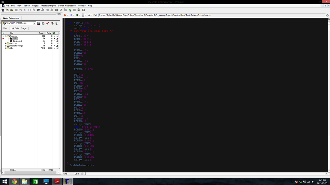
Figure 2: this is a screen shot of the code we used for testing our HCS12
Test Results
After testing our ports we had no issues cycling through each LED. The only issue we did run into was we had a few of the wires crossed on port B which controls which row will be lit up. after switching the pins we had no further issues. we also decided that a delay of 33500 was needed in order to make the LEDs not flicker and look solid.
The following link is for a video of the test results
https://www.dropbox.com/s/ahb1dir3x67xxo1/2015-03-15%2021.54.47.mp4?dl=0
