Background
The transistor circuit consists of 6 transistors which amplify the current from a 5V power rail to a level capable of turning all 24 LEDs in a row on at once. The power rail is ran off the HCS12 5V port. The 1K resistor limits the amount of current that goes through the transistor.
The transistor circuit consists of 6 transistors which amplify the current from a 5V power rail to a level capable of turning all 24 LEDs in a row on at once. The power rail is ran off the HCS12 5V port. The 1K resistor limits the amount of current that goes through the transistor.
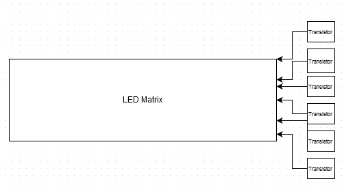
Figure 1: Transistor circuit block diagram
Implementation
The above circuit is connected to the matrix through the 6 header pins that control current to each row. The 5V are supplied from the HCS12 5V port.
The above circuit is connected to the matrix through the 6 header pins that control current to each row. The 5V are supplied from the HCS12 5V port.

Figure 2: Transistor circuit schematic
Test procedure
We needed to ensure the transistor was capable of supplying enough current without exceeding the safe operating conditions. We consulted the transistor datasheet and the maximum current rating is 300mA. We then simulated a row of LEDs in multisim (pictured above) and determined all of the LEDs being on at once produced ~210mA.
Test Results
With the simulation confirming the transistor is capable of powering an entire row we built the above circuit on a breadboard and connected it to the matrix. Once powered, all LEDs in the row turned on.
